|
It was Whiller (1965) who described an indirect type of cooker which could be considered as the precursor of Brace Research Institute Cooker. Whiller’s design has been designated here as Type IDT 1, Figure 52.
Source:- TIDE., March 1998, 8-1, pp 1-37, For Comments, suggestions, contributions contact Please add,Solar or Solar Cooker, in the subject to avoid your mail being erased as scam
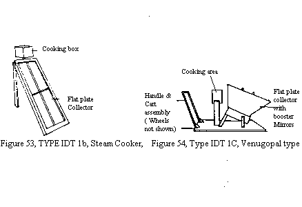
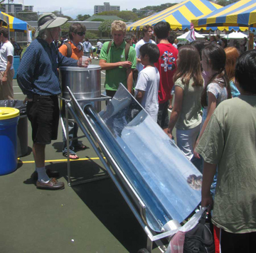
The cooker is simple. A central finned pipe, connected to an insulated cooking box inside the house, is heated by cylindro-parabolic mirror. This boils the water in the finned pipe and the heat is used for cooking. Reports indicate that the cooker did not perform well (Lof 1963). The Brace Research Institute (1972) developed a cooker on these lines and it was called the steam cooker (IDT 1b, Figure 53). Here, the heart of the cooker was a double glazed flat plate. It heated the enclosed water to boiling and heated the insulated box kept inside the house. The cooking vessels could be kept inside this insulated box. Though interesting the design did not perform well (Bowman, Blatt 1978), and Bowman tried to improve the design by altering the connection between the heater and the insulated box so that the heater could be tilted to face the sun. In India, Venugopal (1978) proposed a very promising variation, wherein he attached four reflector boosters to the flatplate collector. (Type IDT 1d, Figure 54). The whole assembly was on a wheeled platform for easy mobility. The insulated box had a separate chamber for keeping the milk hot. This cooker was designed for the roadside tea vendors. Another variation was reported from Iran (GATE 1979), where the unit was larger and the absorber/heater was kept outside the house.
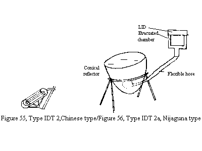
Scientists from China (Fang, Susan 1979) had described another design in 1979 (Type IDT 2, Figure 55). The design incorporated a heat pipe, which is heated by a cylindro-parabolic mirror, with a transparent cover on top to reduce heat loss. This heatpipe delivered the heat to an insulated box kept inside the house. With tracking concentrator and suitable heat transfer fluid inside the heat pipe the design should work well, provided, the reflector has a 2 sq. m surface.
Nijaguna (1983) from Karnataka Regional Engineering College, Suratkal, has evolved a cooker using a heat pipe (Type IDT 2a, Figure 56). A conical reflector covered with a transparent cover heats a heat pipe which in turn delivers heat to an insulated box kept inside the house.
In 1961, Stam presented another interesting and ingenious design (Type IDT 3, Figure 57). The central pipe containing oil was heated by a cylindro – parabolic mirror. This hot oil would then transfer heat to a cooking vessel. The insulated box had a depression to accommodate the vessel. He had also evolved a very simple orientation mechanism for the mirror similar to one mentioned by Von Oppen (1977)
Swet (1972) proposed another design (Type IDT 4 , Figure 58) which was very much similar to the Stam design but the tracking was done with the help of a bi-metallic heliotrope. A bar was provided which cast a shadow on the heliotrope and this setup made the mechanism of tracking more efficient. Test data on this design was not available.
Source:- TIDE., March 1998, 8-1, pp 1-37, For Comments, suggestions, contributions contact Please add,Solar or Solar Cooker, in the subject to avoid your mail being erased as scam
Type IDT5 ( Figure 59 ) was proposed by Beanson ( 1976 ). It was supposed to supply heat for 24 hours a day. Once again the centre of the cooker was a pipe heated by a cylindro-parabolic reflector. The heat transfer medium suggested was oil and the hot oil circulating in a close loop was to accumulate in an insulated container kept inside the house. which double as a cooking ‘stove’ . The circulation of the oil was effected by a small circulating pump attached to the insulated vessels. The pump would be very useful especially if the collector is kept at a height above the insulated box. Reporters of Mechanix Illustrated, Who tested this design, claim that they could fry potato finger chips. But calculations presented by Walton et al. (1977) indicte that at least 100 litres of oil would be required to store sufficient heat to be able to cook in the evening, and naturally, a very large quantity of oil would be essential to store the heat for 24 hours. A cooker which would require 100 litres of oil and material to heat it to 200 C would be very costly.
A group from Haiti, has announced a new design called as Blazing Tube solar cooker. Which uses about 4 feet long CPC type reflector of made of high quality metal reflector concentrating solar energy on a triple coated vacuum tube. The system holds about just 2.5 lit of vegetable oil. The heated oil is held in a insulated cooking container. It is claimed that the temperature reached is about 177 C(313 F). This I would say, is a major development. It should not be difficult for the developers, to alter the design suitably so as to incorporate the cooking compartment inside the Kitchcen, and also make suitable arrangements to 'hold' the Reflector component out side the wall in such a was as to track the sun. (http://www.blazingtubesolar.com/index.html)
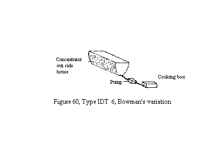
Winston’s compound parabolic concentrators (CPC) have been very popular with the solar water heating enthusiasts, but it was Bowman who designed a cooker on this principle (Type IDT 6, Figure 60). Such a cooker did not come up to the expectations of Bowman, Blatt (1978). But CPC is a highly acclaimed design and if the cooker is designed with more care it should perform well. However, the comments of Walton et al. (1977) are applicable in this case also so the cooker should not be very large.
Concept XII proposed by the author in 1980, envisaged the use of a cylindro-parabolic concentrator on top of the house. The medium of heat transfer was air. The air thus heated was to be circulated through a small but suitable pump running on solar power, to the insulated cooking chamber kept in the kitchen. Suitable precaution has to be exercised to take care of the pressure that may build up or alternatively more suitable heat transfer medium could be selected. The proposed design has been acclaimed as viable by William Beale of VITA, but he felt that solar sterling engine may not be suitable for circulation of air (Beale 1981). Recently, Olwi et al. (1994) have tested a few designs of this type, but the details are not available.
Chemical types are discussed on next page
Emai :
arkundapur@gmail.com Please add, Solar
or Solar Cooker, in the subject to avoid your mail being erased
as scam
NAVIGATION CHART.
OTHER LINKS
are listed
under S11-References A to W
For details
regarding testing standards for Solar Cookers ( International
Standards ) please
click here
For Comments,
suggestions, contributions contact
Dr.
Ashok Kundapur
Email :
Please add Solar or Solar Cooker in the subject to avoid your
mail being erased as spam
|
For
details regarding testing standards for Solar Cookers ( International
Standards ) please
click here
For Comments,
suggestions, contributions contact
Dr.
Ashok Kundapur
Email :
Please add Solar
or Solar Cooker in the subject to avoid your mail being erased as
spam


